Motor Protection
Introduction
Motors controlled by VFDs and servo drives require additional attention to avoid overvoltage spikes known as dV/dt. Voltage wave reflection is a function of the voltage rise time (dV/dt) and the length of the motor cables. Large distances between a motor and a VFD can cause high voltage spikes that damage motors and lead to early failure.
The challenge for OEMs, system integrators and distributors is to ensure installed motors are well protected from overvoltage. Markets using VFDs have adopted a special motor, better known as a motor rated VFD or inverter duty motor. The motor rated VFD construction can change significantly based on the manufacturer, however following the National Electrical Manufacturers Association (NEMA), the greatest difference between a standard motor and an inverter duty motor is the winding insulation. For example, a nominal 480 Vac drive using a standard grade motor should maintain performance and function with peak voltage up to 1000V. For inverter duty rated motors the acceptable peak voltage is typically 1500V.
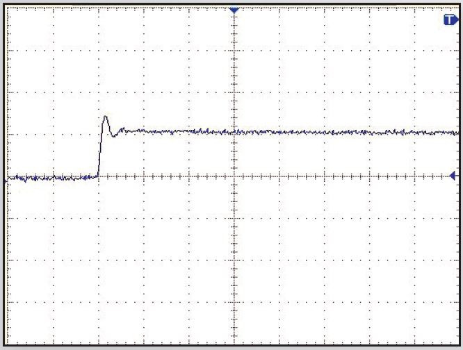
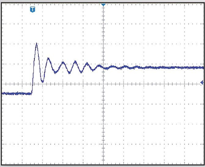
Typical example of dV/dt measured on the motor with cable length 50m (150ft)
Theory
To better understand what causes motor failure and unforeseen challenges it is best to first understand how a VFD is assembled. VFDs are made up of three major parts:
- The rectifier - takes incoming AC power and converts it to DC power.
- The DC link - several capacitors used for energy storage from the output of the rectifier.
- The inverter - produces 2-20 kHz signal used to generate the output waveform to the motor using pulse width modulation (PWM).
PWM is a technique which generates the width of a pulse based on modulation signal information. Due to this technique the dV/dt presents a significant concern.
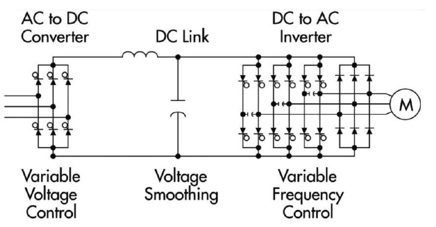
Typical example of VFD layout
The Solution
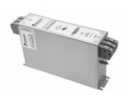
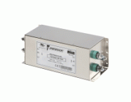
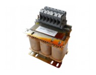
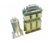
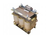
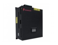
Enerdoor developed the motor protection series to protect motors from harmful overvoltage and dV/dt spikes generated by the drive’s output. This is particularly useful for applications with VFDs, servo drives and long cable applications. Enerdoor solutions are designed to work with various carrier frequencies, output frequencies, and applications and include: differential mode inductance (load reactors), common mode inductance (chokes), sine wave filters, snubbers, and dV/dt filters. This series carries CE and UL approvals and offers a current range from 3 to 1000A with unique features including: high linearity vs frequency and current, very low operating temperatures, and compact dimensions.
Specific Solutions
Sine Wave Filters: This series reduces the effect of the PWM by converting the drives output to a true sine waveform and eliminating dV/dt. Sine wave filters are especially beneficial for long cable applications because they eliminate the need for shielded cable between the drive and the VFD and eliminate the need for a VFD rated motor. Additionally, a sine wave does not emit high frequency emissions and can solve EMC noncompliance issues due to radiated emissions.
The FIN905SF and FIN915SFH sine wave filters reduce the PWM effect, convert the PWM to a sine wave, and eliminate dV/dt. These lines work with applications in open or closed loop feedback. The FIN905SF works with frequency output up to 70 Hz and the FIN915SFH line is used with fundamental frequencies up to 25 kHz and output frequencies up to 3 kHz, while maintaining a very low application temperature.
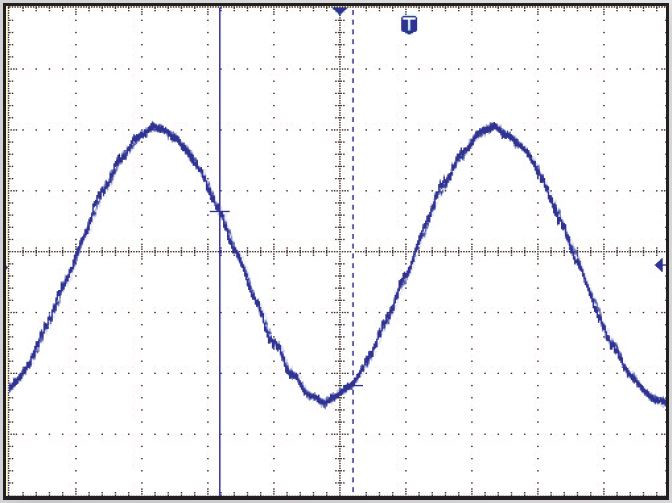
Typical example of a waveform between the VFD and motor using an Enerdoor FIN915SFH sine wave filter
Snubber
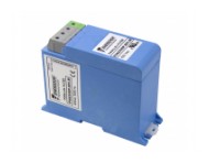
The Enerdoor FIN47SNB snubber is a unique solution to reduce common mode and differential mode noise. The snubber is used in parallel to the system and is an ideal solution for improving the reliability of winding insulation and bearings. It has very low power loss and only one model is needed for unlimited HP motors. The below charts show how the Enerdoor FIN47SNB slows the rate of voltage increase and decreases the peak voltage seen at motor terminals.
Typical measurement of dV/dt on the motor side of VFD with cable length of 100m (300ft)
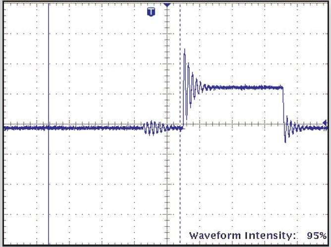
Typical measurement of dV/dt on the motor side of VFD with cable length of 100m (300ft),
with Enerdoor snubber FIN47SNB installed
